Sensor setup
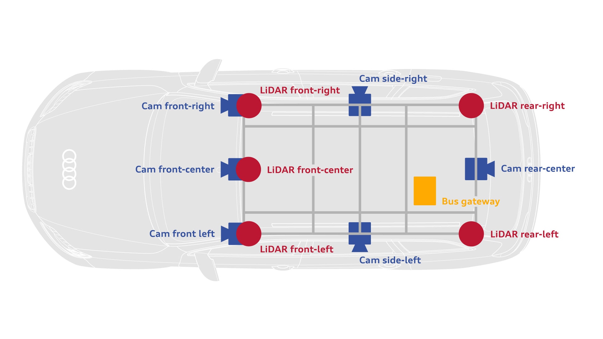
Sensors

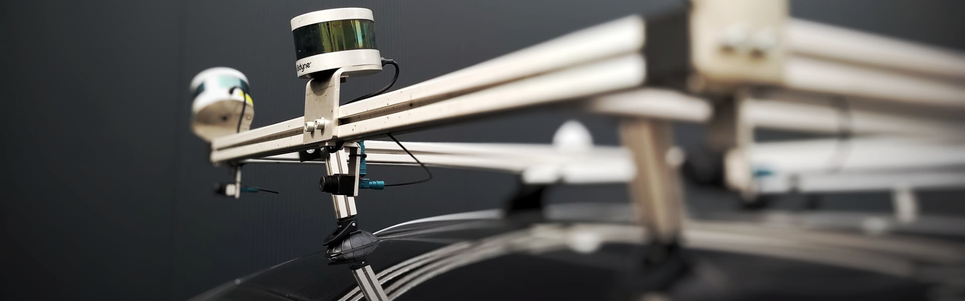
Five LiDAR sensors
- Up to 100 m range
- +/- 3 cm accuracy
- 16 channels
- 10 Hz rotation rate
- 360° horizontal field of view
- +/- 15° vertical field of view

Front centre camera
- 1920 × 1208 resolution
- 60° horizontal field of view
- 38° vertical field of view
- 30 fps framerate
Surround cameras (5x)
- 1920 × 1208 resolution
- 120° horizontal view angle
- 73° vertical view angle
- 30 fps framerate

Bus gateway
- Connected to built-in car gateway
- Connection to all car buses and their sensors
- Timestamping and forwarding of sensor data via Ethernet
Other hardware
Our vehicle is equipped with additional hardware for recording data from the sensor suite and vehicle bus. The cameras are connected to an embedded computer via LVDS, while the LiDAR sensors are connected via a 1G-Ethernet switch. Each LiDAR sensor is connected to a GNSS receiver which acts as a clock. A further GNSS clock serves as a time master for the gateway and embedded computer. The bus gateway connects to the embedded computer via 1G-Ethernet. All data is stored on a crash-safe network storage device, equipped with 48 TB of SSD storage, and accessed via 10G-Ethernet.
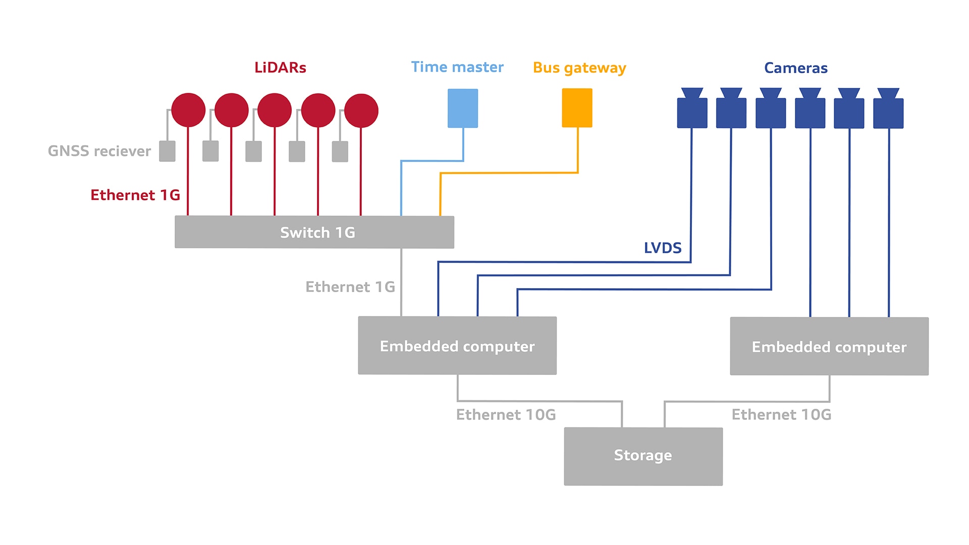
Sensor synchronization
All sensor signals are timestamped in UTC format. Camera images are timestamped when they arrive at the embedded computer, which is synchronised to the time master. Bus data are timestamped at the gateway, which is also synchronised to the time master. LiDAR signals are timestamped at the sensors, which get their time from GNSS.
Calibration
LiDAR-to-Vehicle
The LiDAR sensor pose relative to the vehicle is determined by direct measurement of positions and orientation when mounted on the vehicle.
Camera-to-Vehicle
Camera poses with respect to the vehicle are determined by direct in-situ measurements of position and orientation.
LiDAR-to-LiDAR optimization
We use one LiDAR as a reference and initialise the other LiDAR sensor poses to their measured positions and orientations. Next, an Iterative Closest Point algorithm is used to refine the poses of the other LiDAR sensors within the vehicle coordinate system. This registration uses a recording of a static environment with a static ego vehicle and does not require any fiducial targets.
Camera-to-LiDAR optimization
The camera poses are optimized using camera and LiDAR recordings of fiducial targets (e.g. checkerboards). Additionally a low speed driving scene is used to improve calibration of sensor orientation. This process uses features (e.g. edges) in camera and LiDAR data to optimize relative poses.